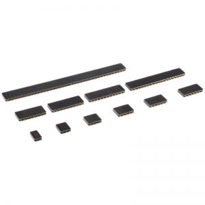
characteristic:
Easy to plug and unplug: The design of the busbar allows components or modules to be easily inserted and removed, making it easy to replace and upgrade.
Standardized spacing: The pin spacing of the busbar usually follows standard dimensions, such as 2.54mm (0.1 inches), 2.0mm, etc., to adapt to different specifications of the busbar.
Multiple configurations: The bus can be single row, double row, or multi row, and the number of pins can also be customized according to needs.
Durability: The busbar is usually made of durable materials and can withstand multiple insertions without damage.
Structural composition:
The basic structure of a busbar includes:
Pin: Usually made of copper alloy, it has good conductivity and elasticity, and the surface may be coated with gold, tin, or other metals to improve performance.
Base: The part that supports the pins, usually made of plastic or other insulating materials. There may be positioning slots or other mechanical features on the base to help with correct insertion.
Fixation method: The busbar can be fixed on the circuit board through Through Hole or Surface Mount (SMT). The plug-in busbar is fixed in the holes of the circuit board by welding, while the surface mount busbar is directly soldered to the surface of the circuit board.
usage method:
Select appropriate bus bars: Select bus bars with appropriate spacing, number of rows, and number of pins according to circuit design requirements.
Install to circuit board: Insert the busbar into the corresponding hole on the circuit board (for direct insertion), or place it in the designated position on the circuit board (for surface mount).
Welding: Use a soldering iron to solder the pins of the busbar onto the circuit board, ensuring that the soldering points are secure and free of short circuits.
Connect the pins: Align the components or modules with pins with the busbar, gently push in, and complete the connection.
Application:
The busbar is widely used in various electronic devices and systems, including:
Microcontroller and sensor module
Prototype development and breadboard experiments
Electronic Education Suite
Industrial control equipment
Consumer electronics products
Due to its ease of component replacement and maintenance, busbar has become one of the commonly used connection solutions for electronic engineers in the design and manufacturing of electronic devices. With the trend of miniaturization and integration of electronic products, the importance of exclusivity in modern electronic manufacturing is increasing.
Shenzhen Baoxin Chuang Electronics Co., Ltd.
Address: 45th Floor, SEG Plaza, 1002 Huaqiang North Road, Futian District, Shenzhen, Guangdong, China
Website: www.boxintron-ic.com
Tel: +86-0755-8355 3623/8322 8690/8322 8629/8322 8357
Fax: +86-0755-8366 0820
Email: service@boxintron.com
Electronic components with a single expert
Shenzhen Baoxin Chuang Electronics Co., Ltd. is committed to becoming the best IC supplier with single expert and IC agent
Strive to provide customers with one-stop electronic components procurement and IC supporting services
Tel: +86-0755-8355 3623 Fax Fox: +86-0755-8366 0820 Email: service@boxintron.com
Address: Room 4503, 45th Floor, SEG Plaza, 1002 Huaqiang North Road, Futian District, Shenzhen, Guangdong, China
![Shenzhen Baoxin Chuang Electronics Co., Ltd. [one-stop type of electronic components with one-only original authentic] Shenzhen Baoxin Chuang Electronics Co., Ltd. [one-stop type of electronic components with one-only original authentic]](templates/web/images/logo.png)